 Substation Power Transformers
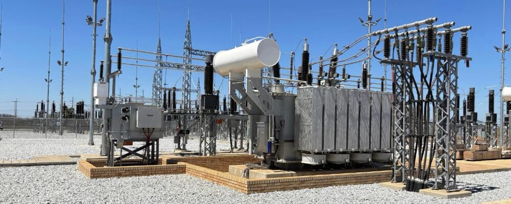
One of the most critical and technically complex items of electrical equipment installed within a substation is the power transformer. In renewable energy facilities, including solar photovoltaic (PV), wind energy and Battery Energy Storage System (BESS) plants, the primary function of the power transformer is to provide the voltage step-up interface between the generation source and the Eskom Transmission or Distribution network.
Electrical energy from renewable generation sources in South Africa is typically collected and delivered to the associated IPP substation at approximately 33 kV. While this voltage is suitable for collection and internal reticulation within the renewable energy facility, this voltage level is not appropriate for bulk power transmission over the Eskom network. Eskom transmission and sub-transmission systems predominantly operate at significantly higher voltage levels, typically 132 kV, 400 kV, and even 765 kV.
To efficiently evacuate power into the Eskom national grid, the power transformer is utilised to increase the voltage from 33 kV to the required grid connection voltage. A transformer is effectively a static electromagnetic device that transfers electrical energy between windings through magnetic induction, enabling voltage transformation without any moving parts. By increasing the voltage and correspondingly reducing the current for a given power transfer, the transformer minimises network losses (I2R Losses), improves transmission efficiency on the overhead power lines, and ensures compliance with Eskom grid connection requirements.
Sizing of Transformers
When selecting and designing a power transformer, one must consider the maximum export capability (MEC) of the renewable plant. Once this is ascertained, the designer would select an appropriate transformer sizing in MVA to allow for the efficient transfer of power. A transformer’s MVA rating indicates the maximum amount of apparent power it can safely transfer under its design operating conditions. While the MVA rating is a key parameter, the actual power that can be delivered also depends on factors such as transformer impedance, system voltage (which influences the transformer’s dielectric strength or insulation), and load characteristics. When sizing a transformer for a renewable energy facility, the required MVA rating is typically determined from the plant’s active power output (MW), while allowing for the power factor and an appropriate design margin. Modern utility-scale solar and wind plants generally operate close to unity power factor, but South African grid code requirements often require additional reactive power capability. As a result, transformers are commonly sized to accommodate operation at power factors between 0.85 and 0.90, ensuring compliance with grid performance requirements while maintaining reliable operation. As a critical link in renewable power generation systems, modern power transformers must also withstand unique challenges such as harmonic distortion from renewable plant inverters, daily thermal cycling, and harsh outdoor environments.
As an example, the basic sizing of a transformer for a 120 MW solar plant would be as follows:

Core and Winding Design
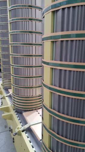
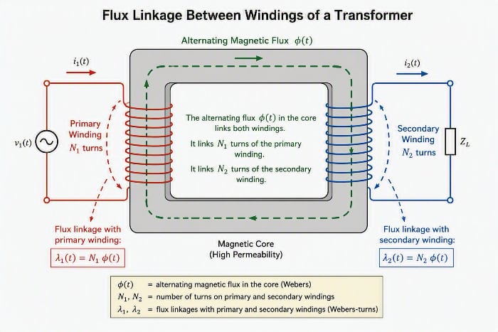
 A transformer’s construction consists of a primary and secondary copper winding that is wound around a magnetic circuit, known more commonly as the transformer core. This steel core is designed to provide a path for the magnetic field to flow around. This magnetic path is necessary for the induction of voltage between the two input and output windings. The transformer core does not transfer power itself; it transfers the magnetic flux that links the windings. The interaction of this alternating flux with the secondary winding induces the secondary voltage and enables power transfer to the connected load. In most types of transformer construction, the central iron core is constructed from a highly permeable material commonly made from thin silicon steel laminations. These thin laminations are assembled together to provide the required magnetic path with the minimum of magnetic losses. The resistivity of the steel sheet itself is high, thus reducing any eddy current loss by making the laminations very thin. These steel transformer laminations vary in thickness from 0.25 mm to 0.5 mm, and as steel is a conductor, the laminations and any fixing studs, rivets or bolts are electrically insulated from each other. The magnetic flux (measured in Webers – Not the braai!) linking the primary and secondary windings travels entirely within the core with no loss of magnetic flux through air.
Transformer windings form another important part of a transformer construction, because they are the main current-carrying conductors wound around the laminated sections of the core. The windings are not arranged with the primary winding on one core leg and the secondary on the other, but instead half of the primary winding and half of the secondary winding are placed one over the other concentrically on each core leg in order to increase magnetic coupling, allowing practically all of the magnetic lines of force to go through both the primary and secondary windings at the same time. However, with this type of transformer construction, a small percentage of the magnetic lines of force flow outside of the core, and this is called “leakage flux”. A transformer steps up (or down) the voltage through the turns ratio between the primary and secondary windings. An AC voltage applied to the primary winding creates an alternating magnetic flux in the transformer core. This alternating flux links both the primary and secondary windings. According to Faraday’s Law, the voltage induced in a winding is proportional to the number of turns on that winding. This is defined in the following formula

The magnetic flux in the core is the same flux linking both windings, but the secondary winding has more turns cutting that flux. Consequently, a higher voltage is induced in the secondary winding. Of course, the transformer is able to work in reverse and can step the voltage down from a higher voltage to a lower voltage with a higher-to-lower turns ratio, thus making it a highly versatile piece of electrical equipment in a power grid.
Tank and Cooling
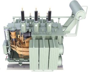
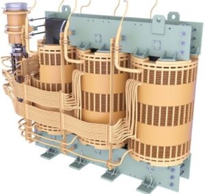 This entire core-and-winding assembly is housed within a robust steel tank filled with mineral insulating oil. The insulating oil performs two critical functions: it provides the dielectric insulation necessary to withstand the electrical stresses present between live components and earth, and it serves as the primary heat transfer medium for removing losses generated within the transformer. During operation, electrical losses in the windings (copper losses) and magnetic losses in the core (core losses) are converted into heat. This heat is absorbed by the insulating oil and, through natural syphon circulation, or via oil pumps in larger transformers, transferred to radiators or heat exchangers, where it is dissipated to the surrounding environment. Effective circulation of the insulating oil is therefore essential to maintaining acceptable operating temperatures and preventing thermal degradation of the insulation system. By controlling the internal temperature rise, the oil plays a vital role in ensuring transformer reliability, performance, insulation life expectancy, and compliance with its specified thermal rating. This is particularly critical in high ambient temperature areas where transformers are installed, e.g., the Northern Cape, where temperatures can exceed 40°C. The level of the oil is assured using the tank one always sees on top of a transformer called the conservator. The conservator not only ensures a constant tank level but also allows the oil to expand and contract with temperature without letting air/moisture into the main tank. Any moisture in the oil can lead to serious flashovers in the internal high-voltage areas of the transformer. The final main components are the medium voltage (MV) and high voltage (HV) bushings to which the power input and output of the transformer are connected. These are normally porcelain (or composite) insulators that let the HV and MV conductors pass safely through the grounded tank wall; the HV bushing being taller because it needs more creepage distance for the higher voltage.
Transformers remain one of the most critical and highest-value assets within a substation. Their correct selection, specification, and design are essential to ensure the safe, reliable, and efficient transfer of electrical power to the Eskom national grid. Beyond the core and windings, modern power transformers incorporate numerous auxiliary systems and protection devices that are vital for performance monitoring, cooling, insulation preservation, and operational safety. These components and their functions will be explored in future articles. With extensive experience across South Africa’s power sector, Tractionel has successfully installed, tested, commissioned, and energised a wide range of power transformers. This practical experience, combined with strong technical expertise, enables Tractionel to deliver transformer projects safely and effectively while ensuring compliance with utility, regulatory, and project-specific requirements.